1. Introduction
As an architecture student, I am well-versed in CAD software, having spent years drafting in AutoCAD and direct modeling complex forms in Rhino. However, my previous experience has been largely visually driven. Currently, my architectural studies involve Grasshopper and Python, introducing me to algorithmic thinking. Using parametric design in FreeCAD feels distinct from Rhino. In Rhino, modifying material thickness often requires a tedious process of redrawing the entire geometry. In contrast, FreeCAD allows me to define mathematical relationships where changing a core parameter automatically updates the whole model. While this direct modeling based on logic and mathematical relationships is somewhat fresh to me, I can clearly see its immense value for efficient design iteration and digital fabrication.
2. Design Concept
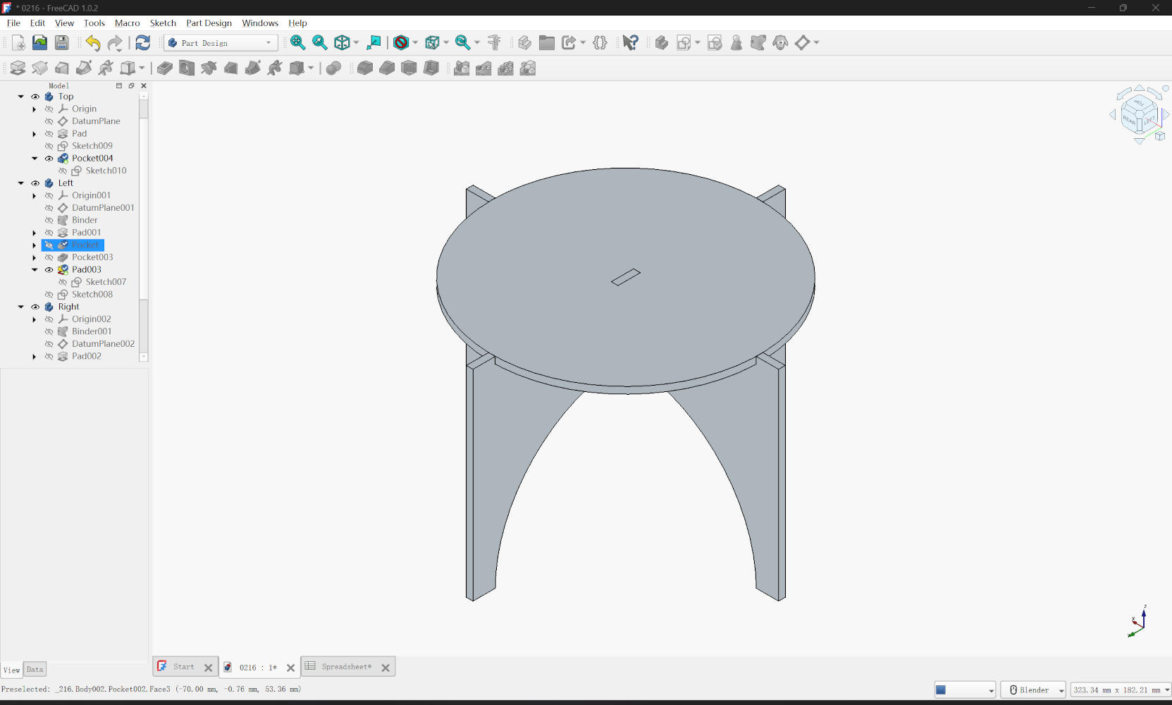
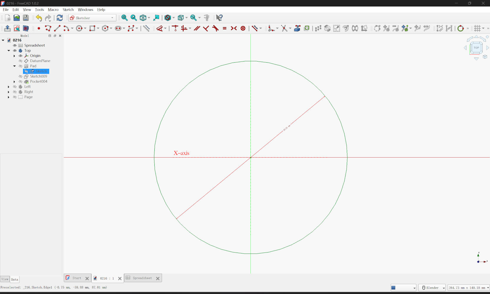
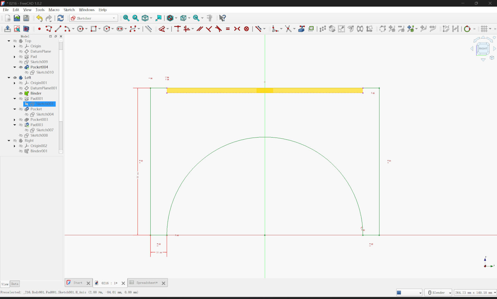
My design goal was to create a table efficiently cut from a single rectangular board. To minimize material waste, I planned to cut a circular tabletop and split the remaining material into three parts to form the legs. Conceptually, this design stems from simple geometry. I started in the Sketcher Workbench to draw these components. For the tabletop, I simply used a circle geometry. For the table legs, I primarily utilized the Polyline tool combined with Arc by center to trace a continuous, organic profile. I also heavily utilized Construction Geometry (blue lines) to define the boundaries of the "stock board" and to ensure the circular cuts were perfectly centered and aligned before converting the main shapes into real geometry for extrusion.
3. Sketching & Constraints
Achieving a "fully constrained" sketch (where the lines turn green) was a rigorous yet highly rewarding process. I relied heavily on Parallel and Equality constraints to maintain symmetry between the legs without defining every single line individually. Since I had pre-calculated the dimensions for the straight edges and arcs, I applied dimensional constraints accordingly. I occasionally encountered the "over-constrained" error, which was frustrating at first. However, I learned to troubleshoot this by reading the Solver's error messages, deleting redundant dimensional constraints, and simplifying the geometric logic until the sketch became stable and fully defined again.
4. 3D Modeling
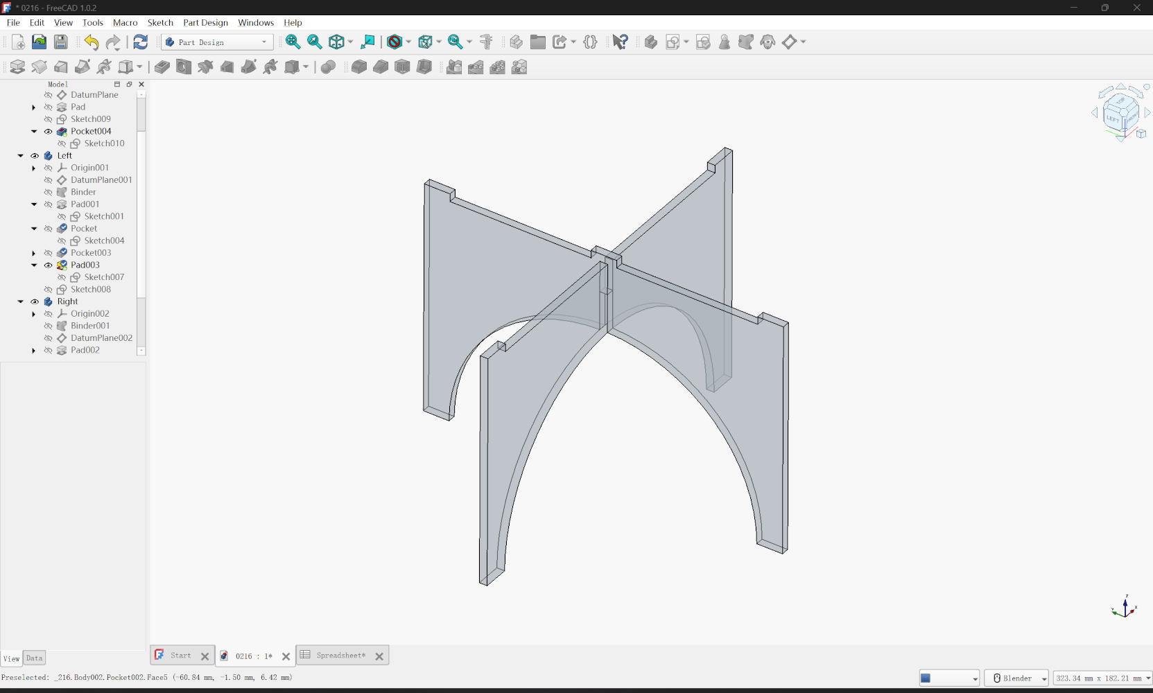
Once the sketches were fully constrained, I closed the Sketcher and moved to the Part Design workbench to generate the 3D forms. For the tabletop, I used the Pad tool to create the base thickness, followed by a Pocket operation to carve out a rectangular slot in the center. To ensure easy assembly, I modeled the two leg parts in separate bodies. After padding them into solids, I used Pocket to create the necessary slots for the tabletop and the interlocking joints between the legs. Finally, to satisfy the requirement for additive features, I sketched on the surface of one leg and used Pad to create a small protrusion designed to lock securely into the tabletop's recess.

5. Parameters
Since the design is based on a single board, I didn't need an overwhelming number of parameters. First,
I defined a critical parameter named material_thickness and set it to 3mm. Next, I defined parameters
for the stock material: board_width and board_length. I also added parameters for the table_diameter and
leg_width. In the sketch, I linked the dimensions to these aliases. For example, instead of typing a
fixed height for the legs, I used the expression editor to set the leg height to exactly
automatically.
Download
Project Files (.zip)