1. Fabrication Objectives
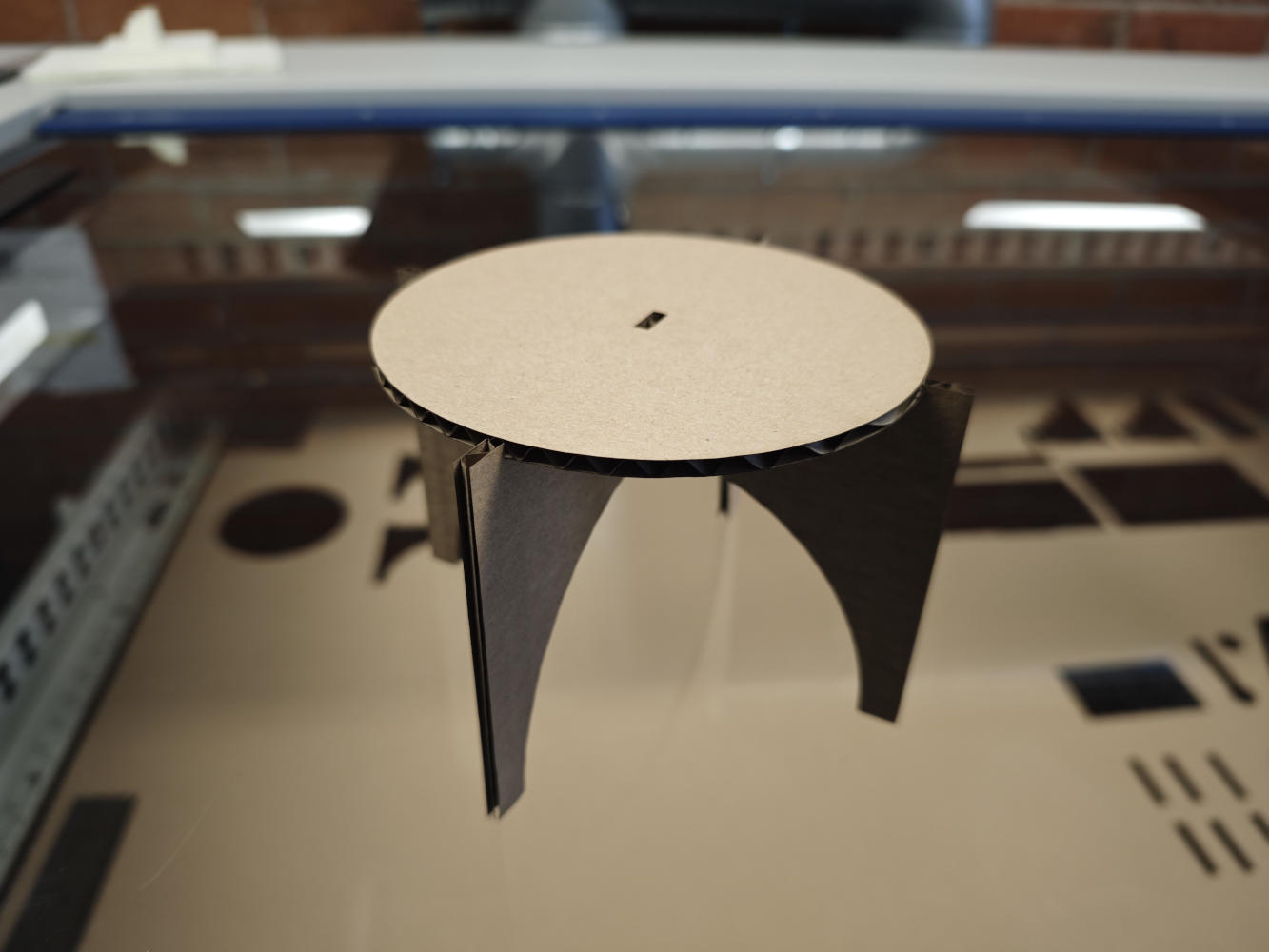
My objective for this assignment was to fabricate the parametric table I designed previously. The design comprises a circular tabletop and leg components, meeting the requirement of having at least three parts cut from the same sheet. The core concept relies on a press-fit construction, where the legs interlock with the tabletop and each other using carefully designed slots. I aimed to create a stable structure assembled purely through friction and geometry, without any glue or fasteners. Although my original design optimized material usage by nesting all three components within a single square board to minimize waste, I ultimately decided to cut the parts separately during this session.
2. Parameter Adjustment
Initially, I had modeled the design assuming a standard material thickness of 3.0mm. However, the instructor helped me measure the actual cardboard stock using a digital caliper, and we discovered its true thickness was 3.4mm. Instead of manually redesigning each part, I simply opened my FreeCAD spreadsheet and updated the material_thickness parameter from 3mm to 3.4mm. I immediately verified that the 3D model updated correctly: the widths of all interlocking slots automatically widened to accommodate the new dimension. This quick adjustment saved me significant time and ensured a proper fit for the physical object.
3. File Preparation
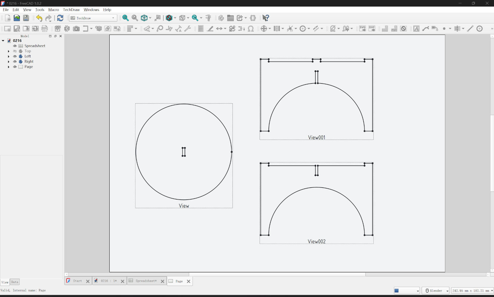
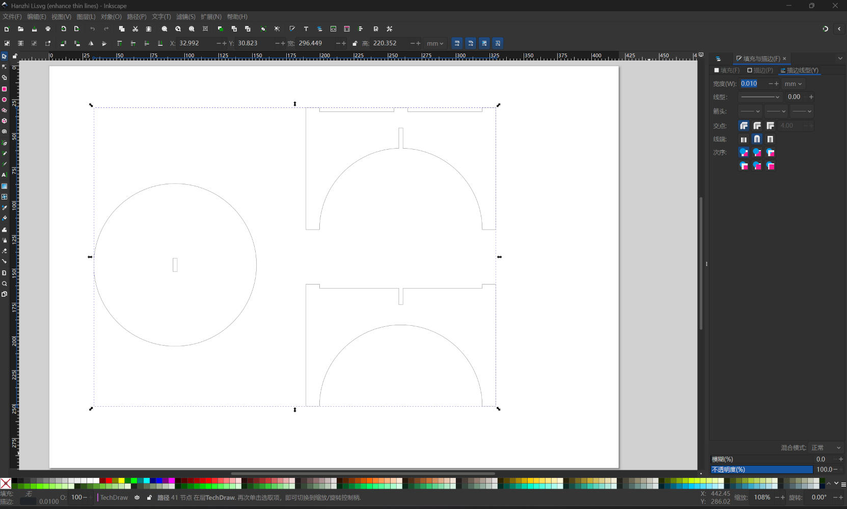
To prepare the cutting files, I used the TechDraw Workbench in FreeCAD. I inserted a default page and projected 2D views of my 3D components (tabletop and legs) onto it, exporting the result as an SVG file. Next, I opened the SVG in Inkscape for final processing. My file imported remarkably cleanly, requiring minimal path joining operations. I followed the standard workflow diligently, ensuring there were no overlapping lines or duplicate paths, which is crucial to prevent the laser from cutting the same path twice and potentially damaging the material or the machine.
4. Laser Cutting & Assembly
In Inkscape, I selected all cutting vectors and set the stroke width to exactly 0.01 mm. This is a
critical step for the machine to recognize the lines as vector cuts. Since my design did not include
text or decorative markings, I did not need to use color mapping; I simply set all cutting lines to
black. I sent the job to the Epilog Dashboard, selected the standard presets, and initiated the cut. The
machine cut through the 3.4mm cardboard cleanly and efficiently. The final assembly was very smooth;
hold their shape firmly, but loose enough to assemble without crushing the cardboard structure.
Download
Project Files (.zip)