1. General Electronics Production
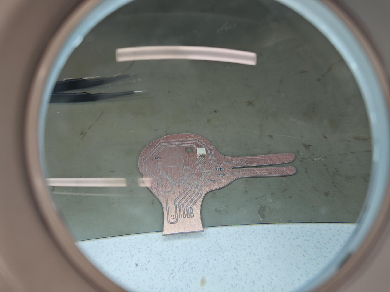
To bring my interactive "duck-rabbit" board to life, I explored electronics production. In the commercial industry, Printed Circuit Boards (PCBs) are typically manufactured using chemical etching, solder masks, and silkscreens on FR4 fiberglass substrates. However, for rapid prototyping at the Fablab, we use CNC milling on safer FR1/FR2 phenolic paper copper-clad boards to avoid producing hazardous fiberglass dust. This in-house subtractive manufacturing process is incredibly empowering. It allows me to quickly iterate on my interactive art installations, test the physical fit of my custom-shaped PCBs, and ensure my electronic logic works before committing to expensive, time-consuming external fabrication.
2. PCB Milling and Gerber Files
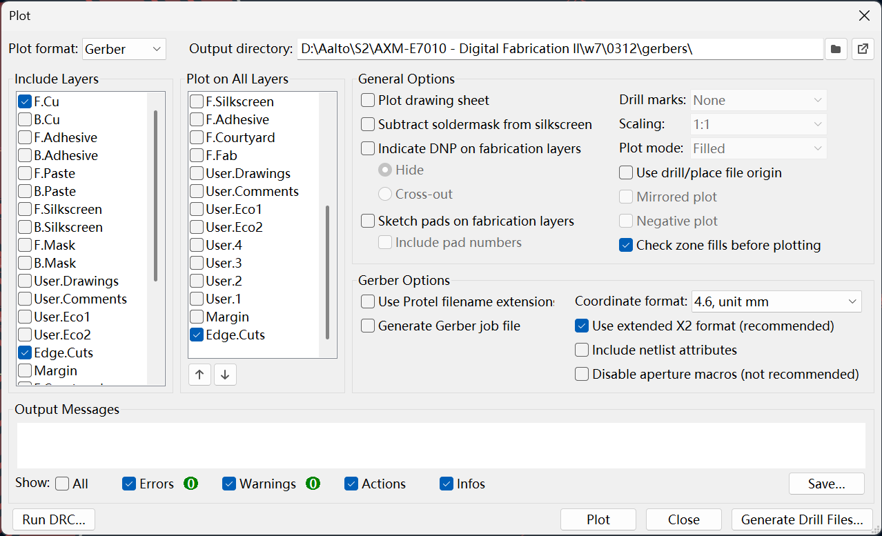
The standard format for PCB manufacturing is the Gerber file (specifically X2 format), which stores 2D graphical data for copper traces, drill holes, and edge outlines. In KiCad, I plotted these Gerber files and converted them into machine-readable toolpaths. For isolation milling, the software calculates paths around the traces to isolate copper islands. A critical issue during toolpath generation is ensuring the tool diameter matches your design's clearance; I previously set my Net Classes to a 0.4mm clearance. I generated paths using a 60-degree V-bit for engraving the fine traces and a 0.8mm cylindrical bit for drilling holes and contour cutting my custom duck-rabbit outline.
3. Actual Milling Process
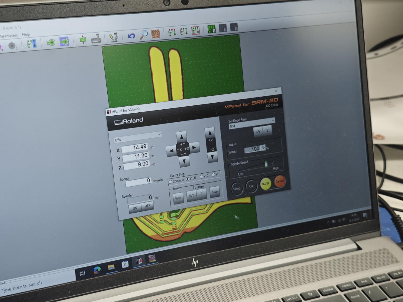
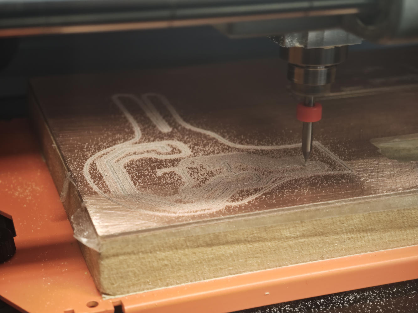
For the actual milling process, the teaching assistant mostly helped me operate the Roland monoFab SRM-20 CNC machine. We secured a piece of FR1 single-sided copper board to the machine's sacrificial bed using double-sided tape. Using the machine's control software (VPanel), the X, Y, and Z origins were carefully set to a clear area on the board. After setting the zeros, we loaded my engraving toolpath. Once the traces were done, the machine was paused to swap to the 0.8mm bit (re-zeroing the Z-axis), and then ran the drill and outline cut jobs.
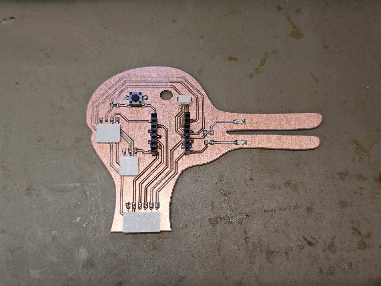
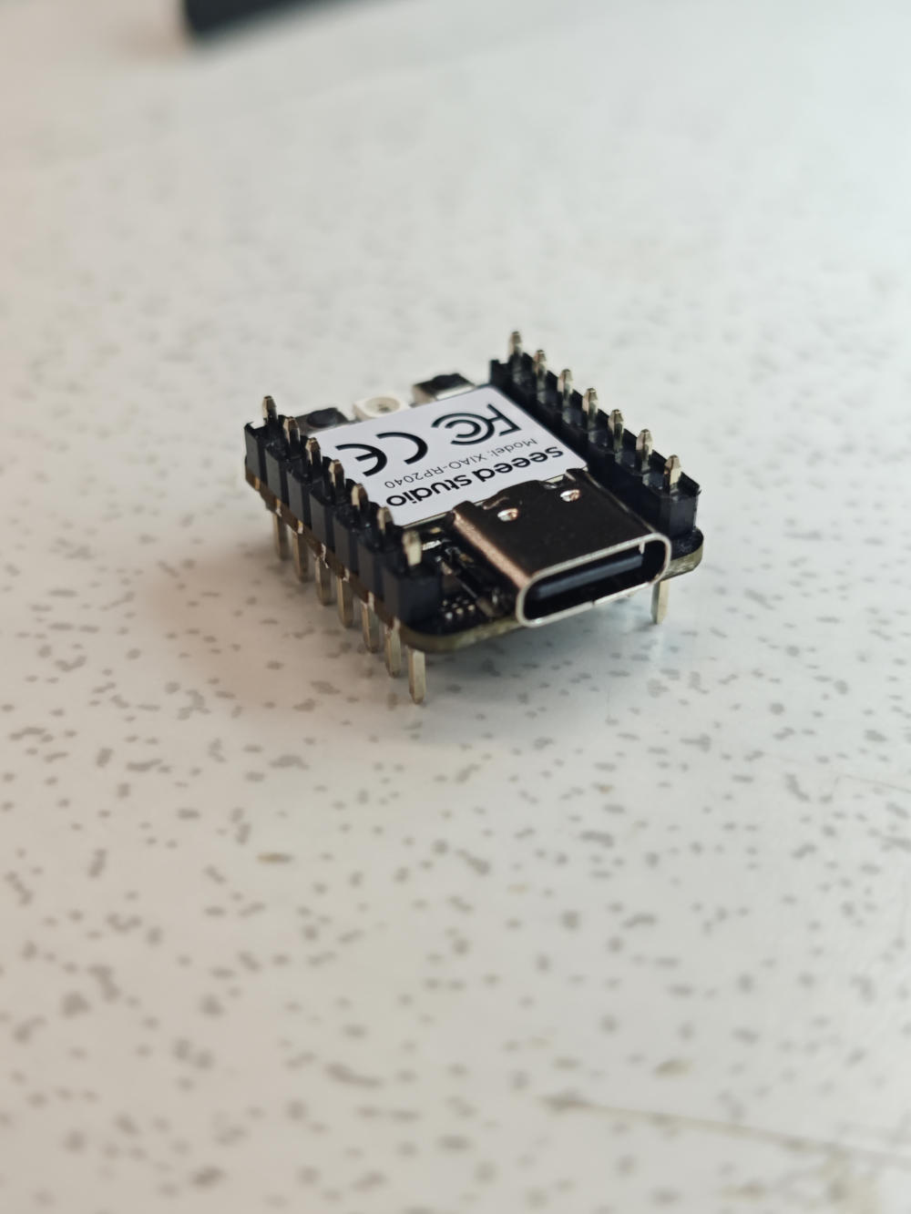
4. Assembly and Soldering
With the milled board ready, I moved to the soldering station. I populated the board with a Seeed XIAO RP2040, two 1206 LEDs with 100-ohm current-limiting resistors, an Omron tactile button with a 10k-ohm pull-up resistor, a 4-pin horizontal SMD connector for I2C, and female headers for UART and GPIO_Ext. The biggest problem I encountered was that I accidentally soldered the pin headers on the XIAO module completely backwards! Thought this was my smoothest soldering to date. Fortunately, despite the reversed orientation, it still works perfectly when plugged in. Finally, I used a digital multimeter's continuity mode to ensure there were no bridged connections or short circuits between the 3V3 and GND lines.
5. Programming and Testing
Finally, I wrote a MicroPython script in the Thonny IDE to test the board. My goal was to read the tactile button and drive the two LEDs. Because the RP2040 chip handles the logic, I programmed a state machine so that pressing the button transitions the LEDs (on pins D0 and D1) between three states: completely off, alternating blinking, and solid on. I used time.ticks_ms() for non-blocking delays to ensure the button (on pin D10) remained responsive and wasn't interrupted by time.sleep(). The code uploaded successfully, and my duck-rabbit board functioned perfectly on the first try.
from machine import Pin
import time

led1 = Pin(26, Pin.OUT) # D0
led2 = Pin(27, Pin.OUT) # D1
btn = Pin(3, Pin.IN, Pin.PULL_UP) # D10

state = 0
last_btn_state = 1
last_blink_time = time.ticks_ms()

led1.value(0)
led2.value(0)

while True:
    current_btn_state = btn.value()

    if current_btn_state == 0 and last_btn_state == 1:
        state = (state + 1) % 3
        time.sleep_ms(50)

        if state == 0:
            led1.value(0)
            led2.value(0)
        elif state == 1:
            led1.value(1)
            led2.value(0)
            last_blink_time = time.ticks_ms()
        elif state == 2:
            led1.value(1)
            led2.value(1)

    last_btn_state = current_btn_state

    if state == 1:
        current_time = time.ticks_ms()
        if time.ticks_diff(current_time, last_blink_time) > 500:
            led1.toggle()
            led2.toggle()
            last_blink_time = current_time

    time.sleep_ms(10)